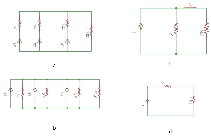
Let us consider the circuit in Figure 27a.

Converting voltage sources to the current sources we achieve the scheme in Figure 27b. All the current sources are form one equivalent current source I, where:
Thus:
This means that n parallel voltage sources can be replaced with one current source or voltage source.
Current in the external network is the following:
Voltage between two nodes can be found the following way:


